The Engine Roars to Life

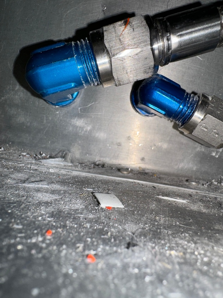
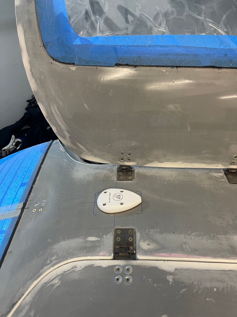
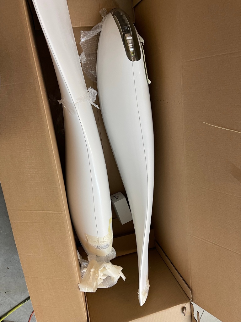
In prepping for first engine start, I first had to get fuel flow testing done. I started out by putting 5 gallons of fuel in each tank sloshing it around a bit and draining it back out by pulling the sump drain. This flushed the tank of any construction debris, which there were only a couple of small metal chips found.

For safety sake, I had my extinguisher out and ready at all times, and I also bought a metal funnel which I bolted on a wire to with an alligator clip on the other end to ground to the airplane skin. On this same bolt, on the inside of the funnel, I attached a long piece of safety wire which went down through the funnel and was extra long to sit inside the container catching the fuel so it was touching the liquid as well. I also grounded the airplane with a separate wire to the metal hangar building, although this is less important as it is to have the funnel and container/liquid at the same potential as the airplane so no static can build up.

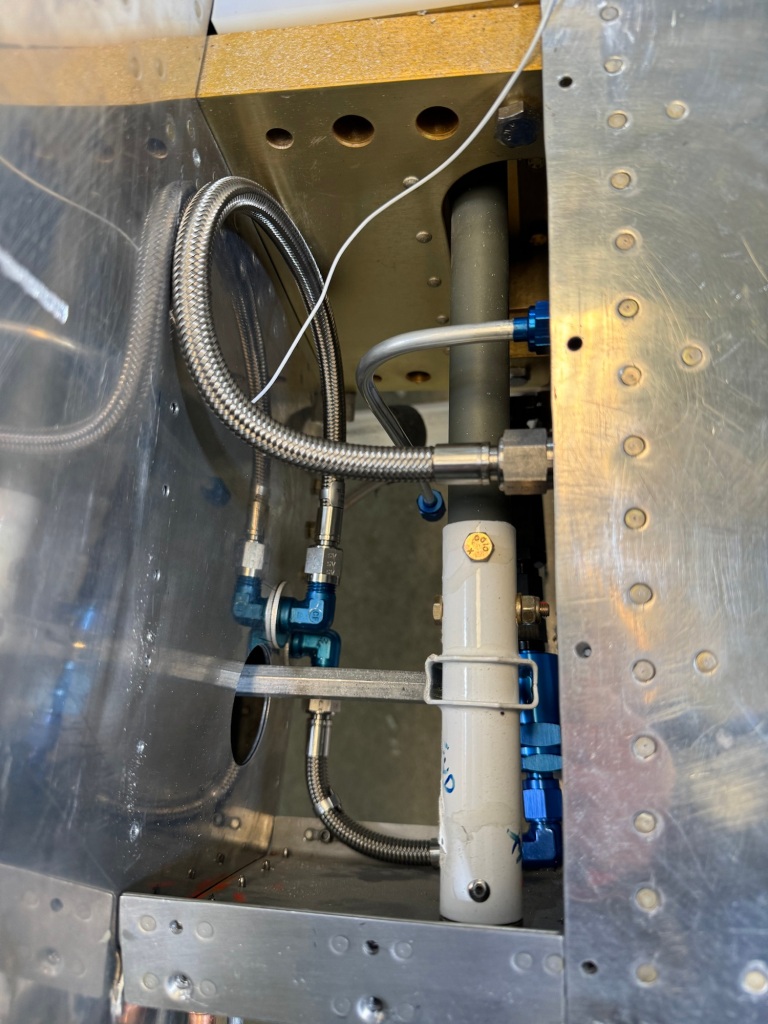
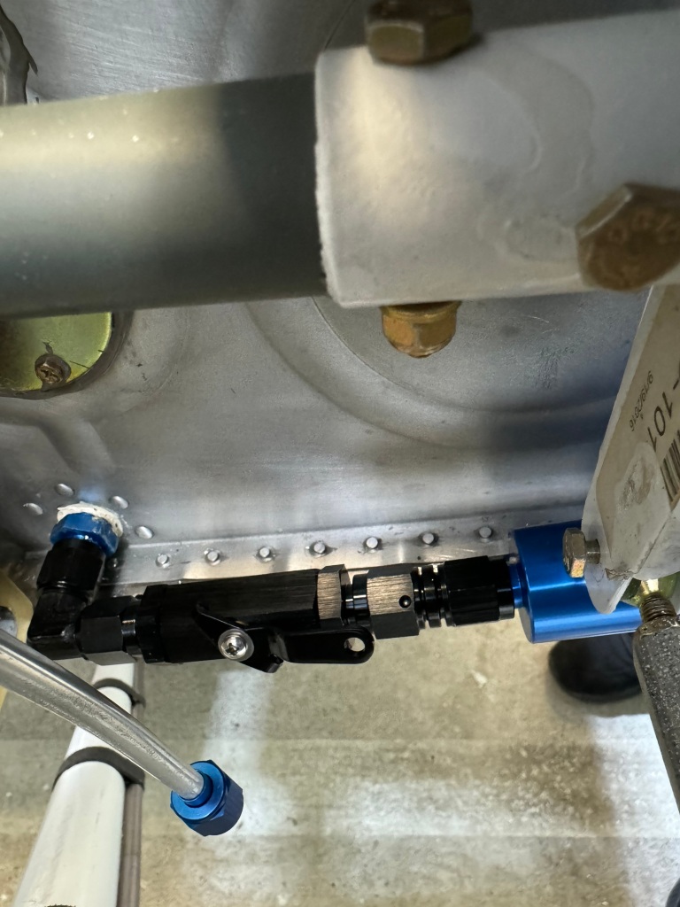
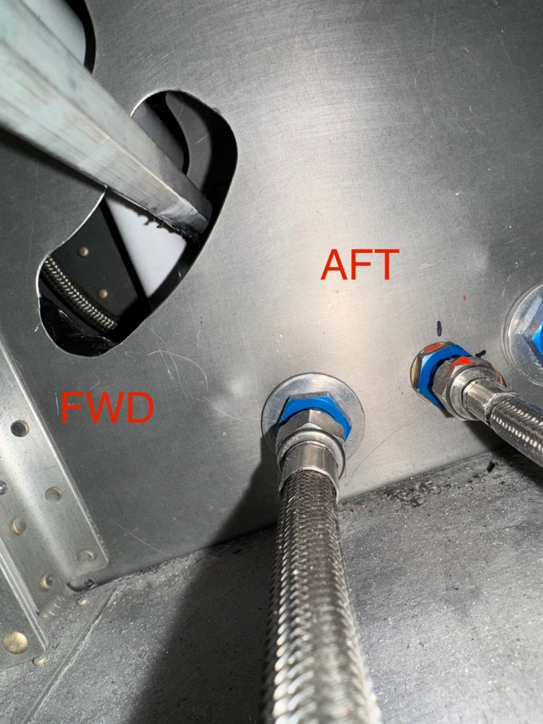
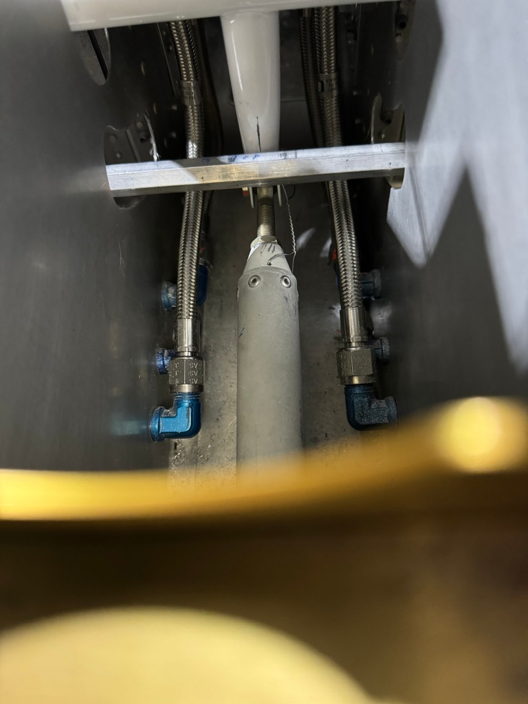
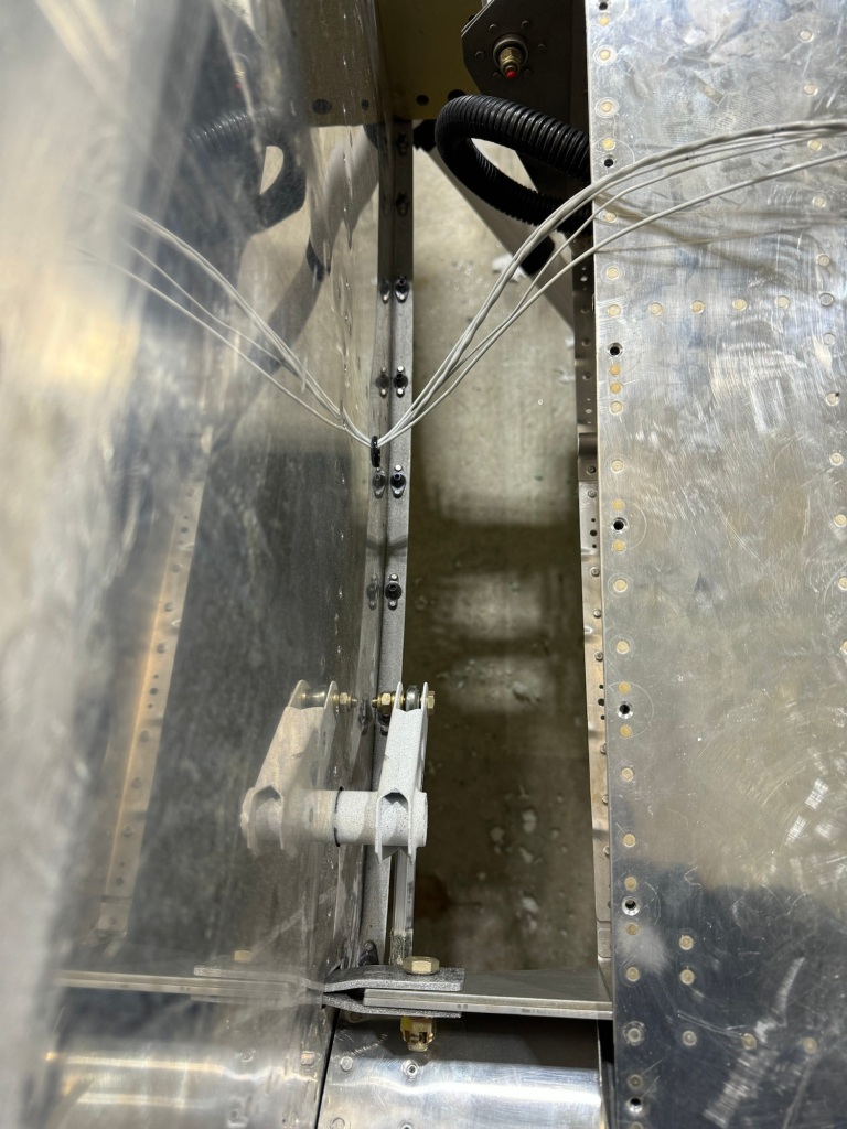
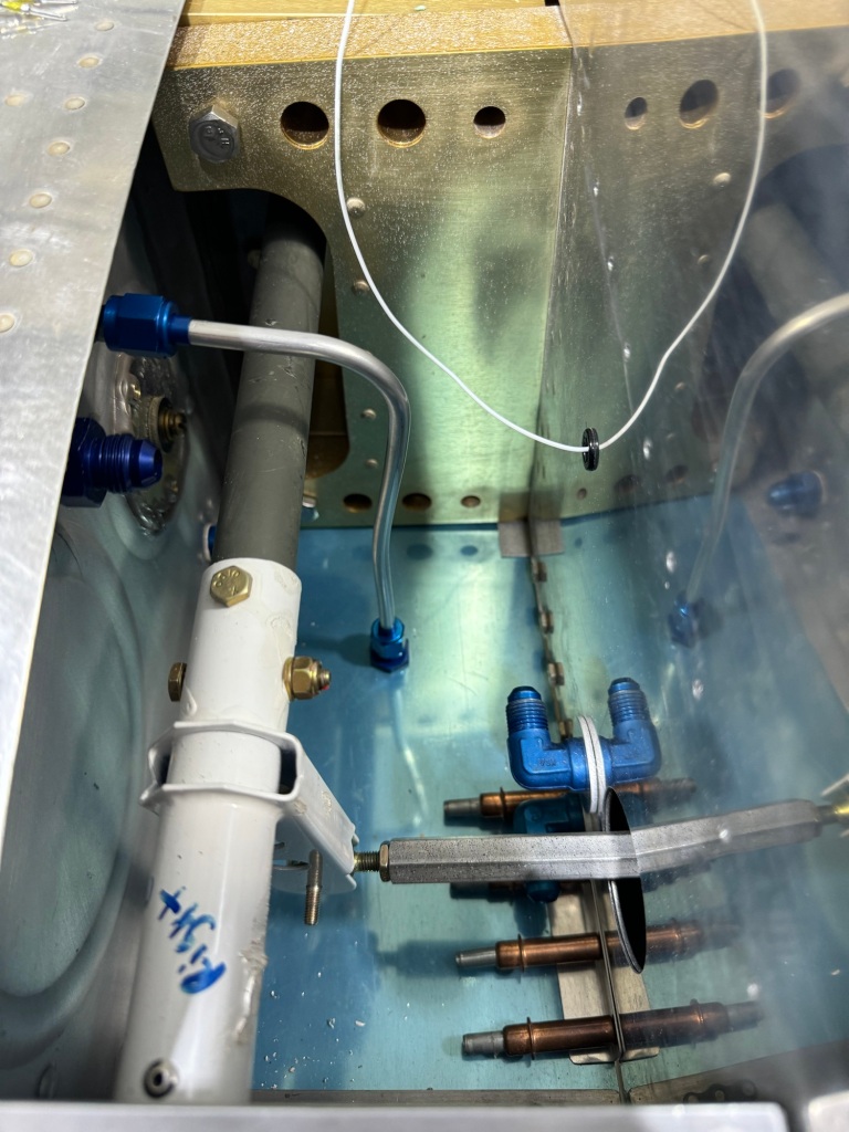
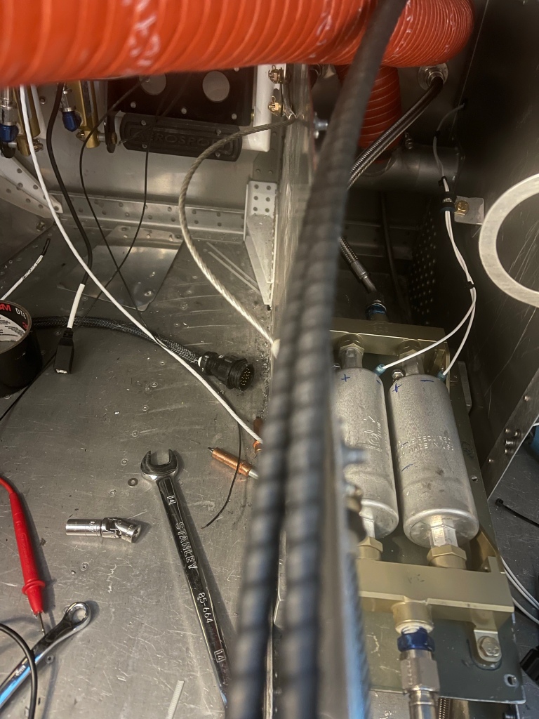
I then put 5 gallons back into each tank and ran each fuel pump, checking for leaks as fuel was circulating through the whole system. I adjusted my fuel pressure regulator to 46psi statically with the engine not running.

Fuel Pressure!

Then it was on to the fuel flow tests. First I pumped all the gas out by unhooking the return hose and running the pump until it cavitated. Then I collected what was left in the tank via the drain sump. A very small amount was left in each tank.

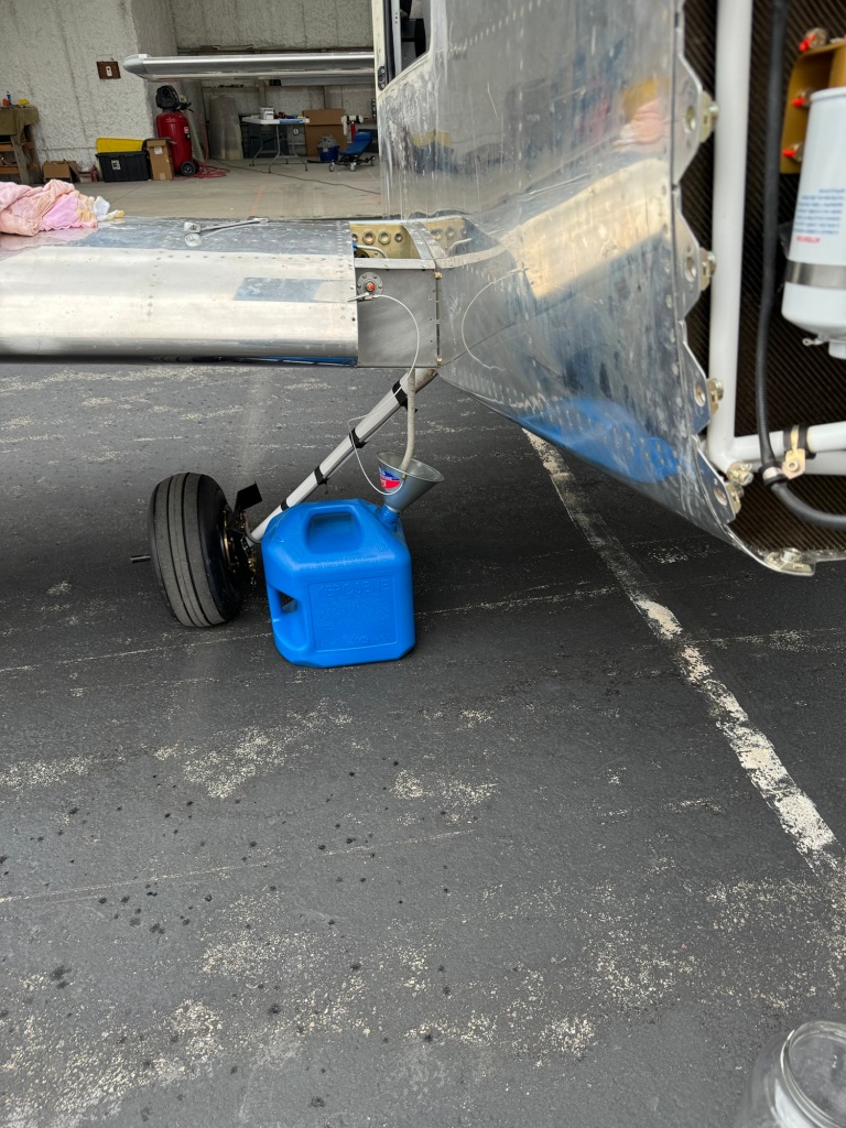
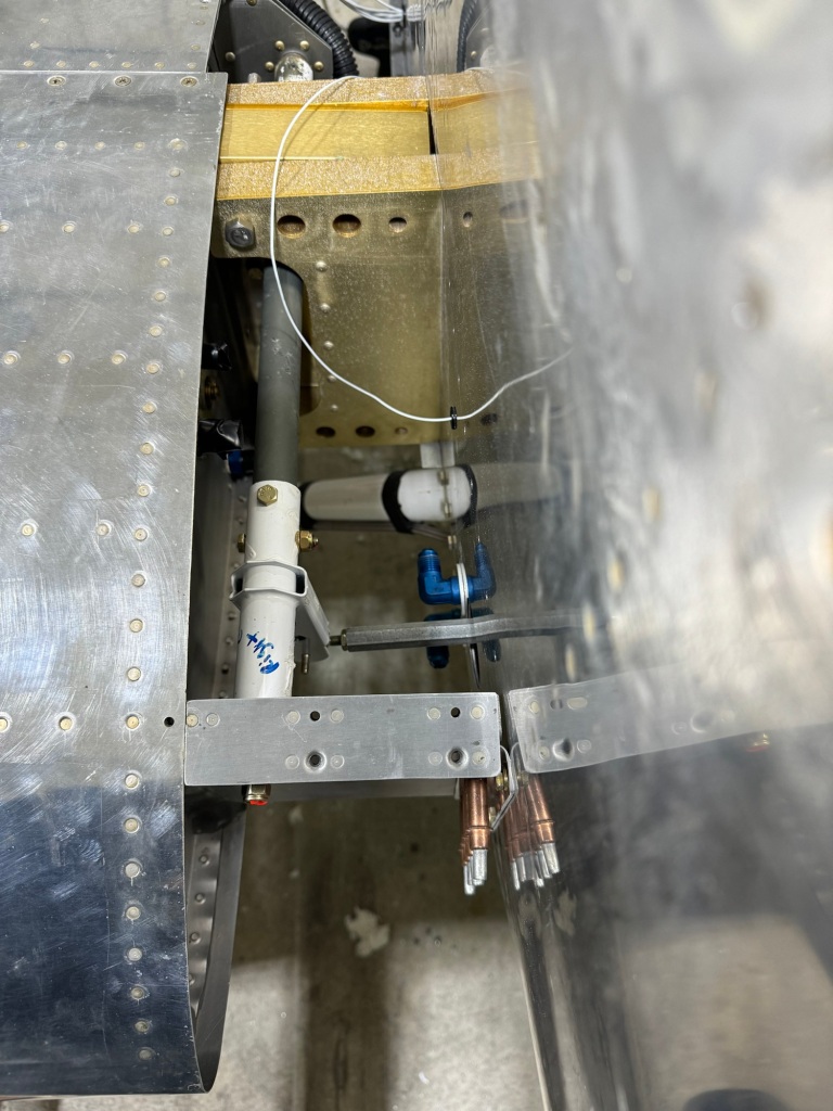
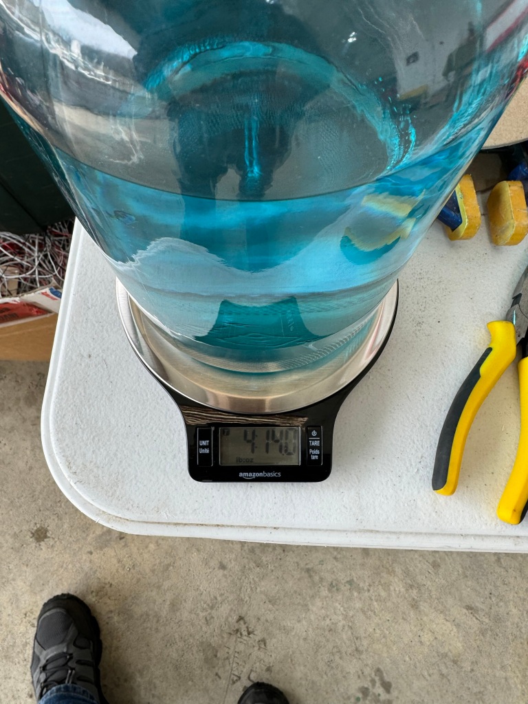
Then fuel was added back to the tank and again the return hose was used to fill a 1 Gallon glass container while the pump ran for 1 minute in a flight level attitude. I almost filled the 1 gallon in a minute.

Weighing it, I got a little over 4 lbs. Avgas is around 6 lbs/gal and the temps were in the high 40’s low 50’s, so the density of the fuel should be close to the 6 lbs/gal. Doing the math to convert weight per minute to gallon per hour nets me > 48 Gallons per hour delivery. I did each tank twice once from each fuel pump to make sure each pump can deliver at least 150% of what the engine needs at full power.

I then lifted the nose up as much as I could before the tail hit to simulate a nose up attitude. The 4 tests were repeated and netted close to the same results.

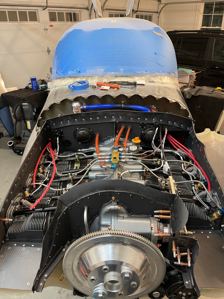
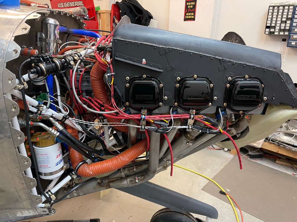
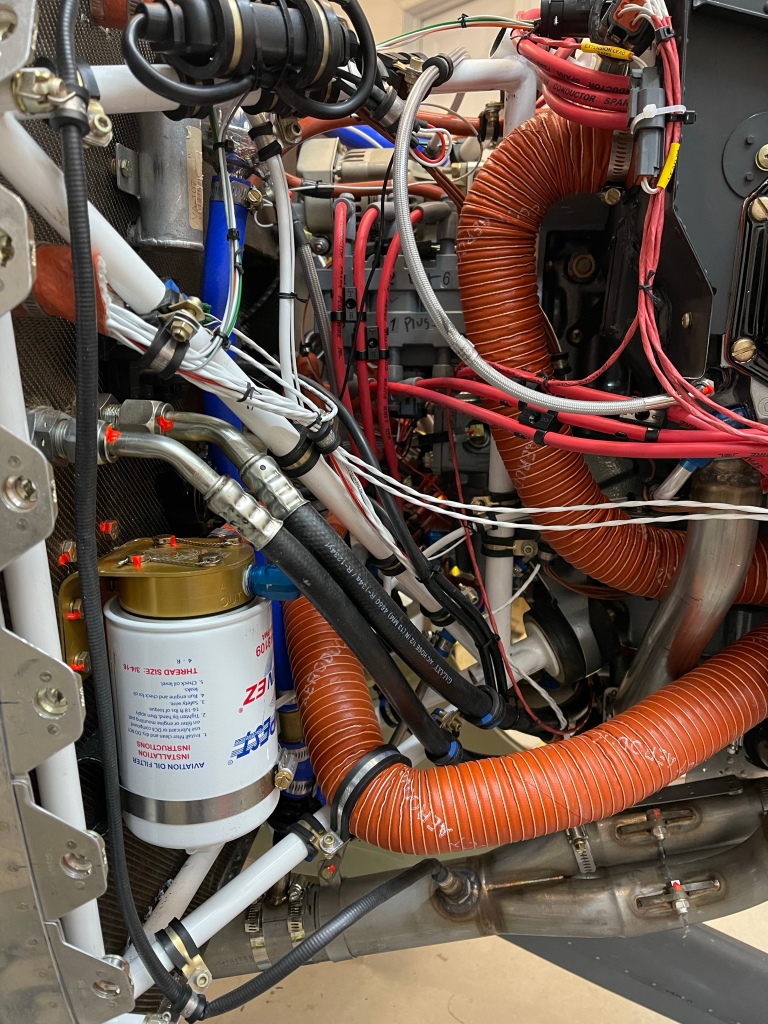
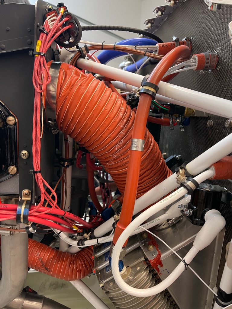
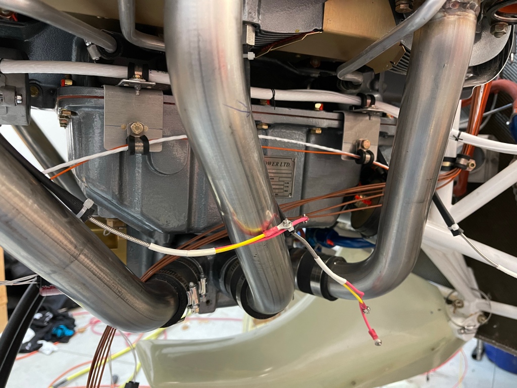
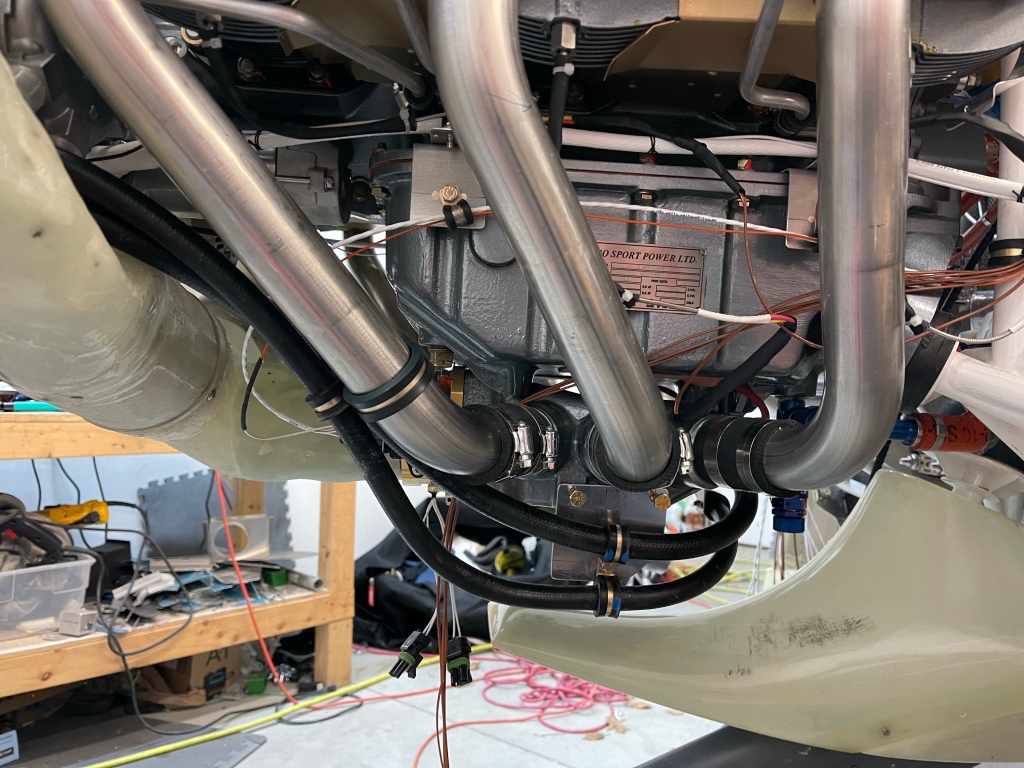
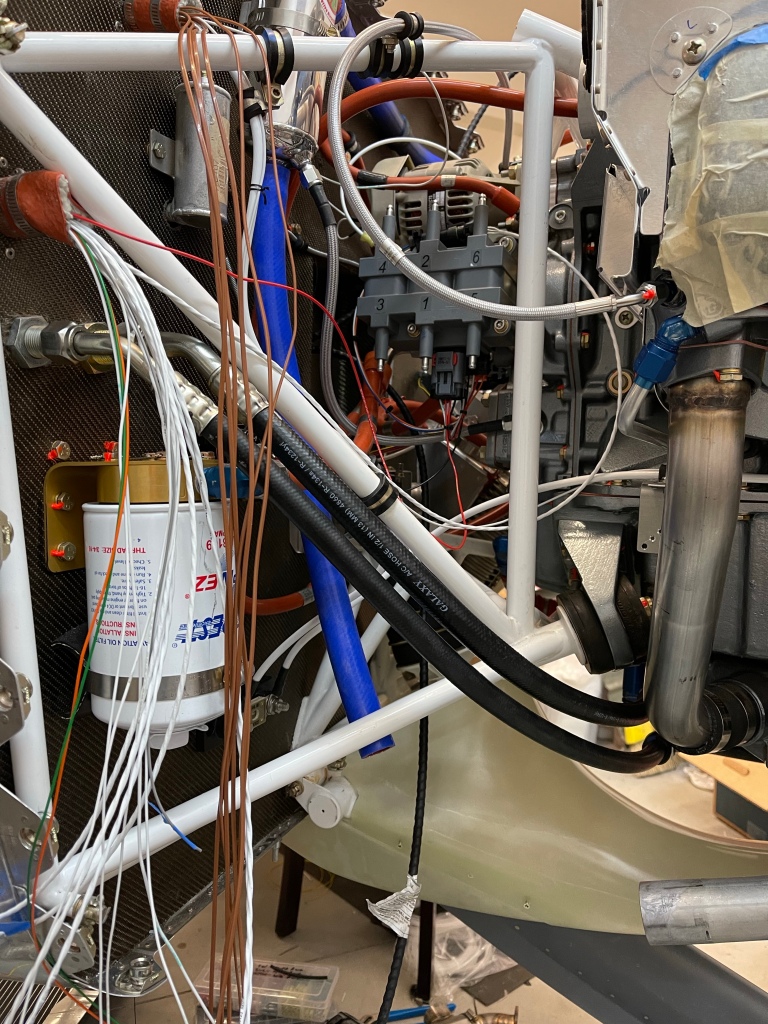
Then it was on to putting oil into the sump and filling the oil cooler.

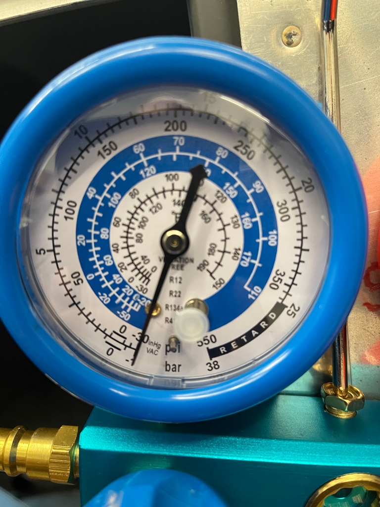
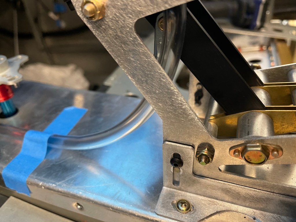
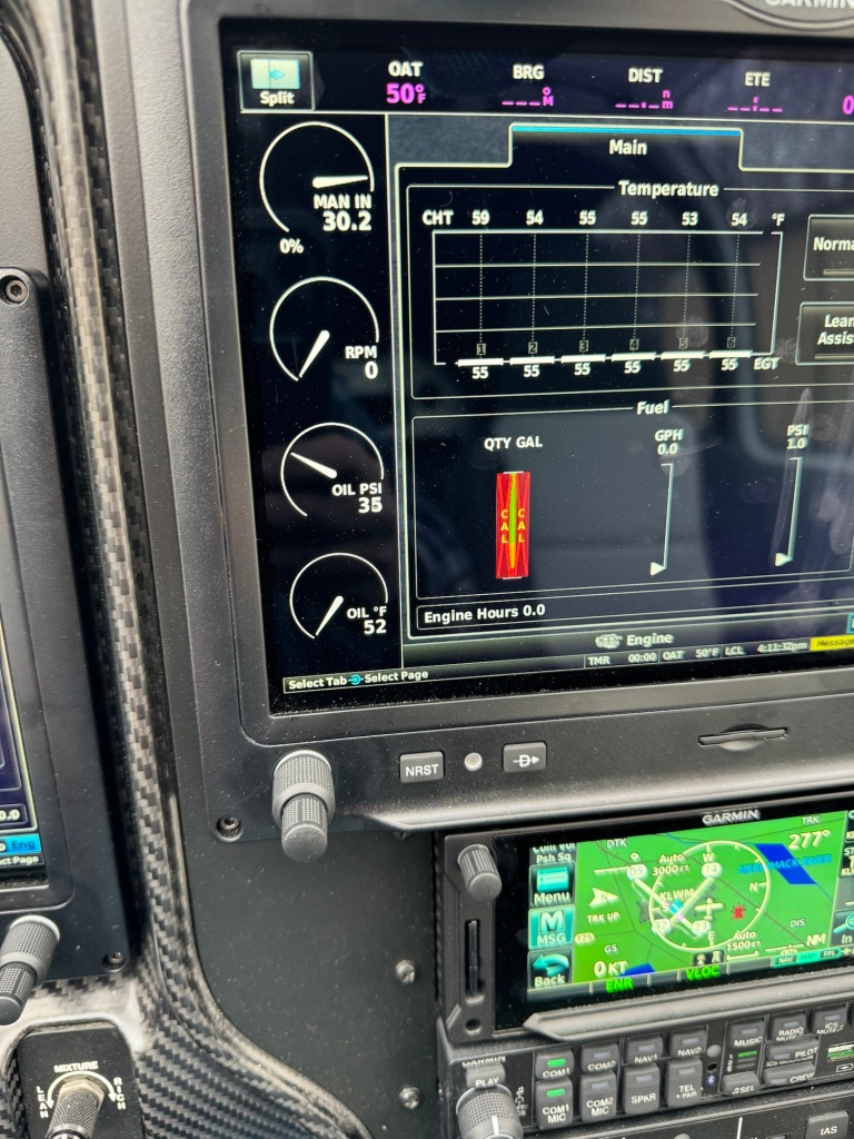
Once things were oiled up, I left the top plugs out, disconnected the bottom plug wires, shut off the fuel and ignition, and cranked the engine to pre-oil the engine. This ends when you start to build up oil pressure as shown below.

Oil pressure

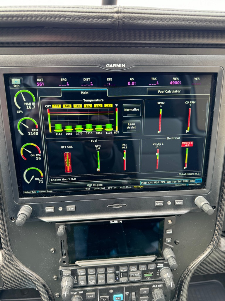
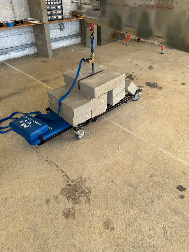
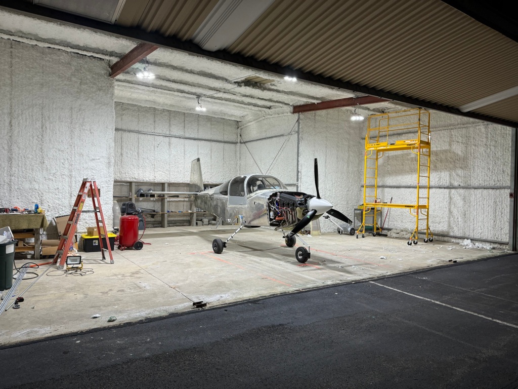
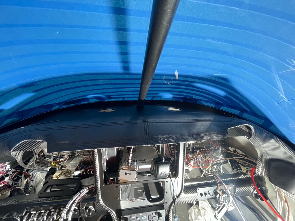
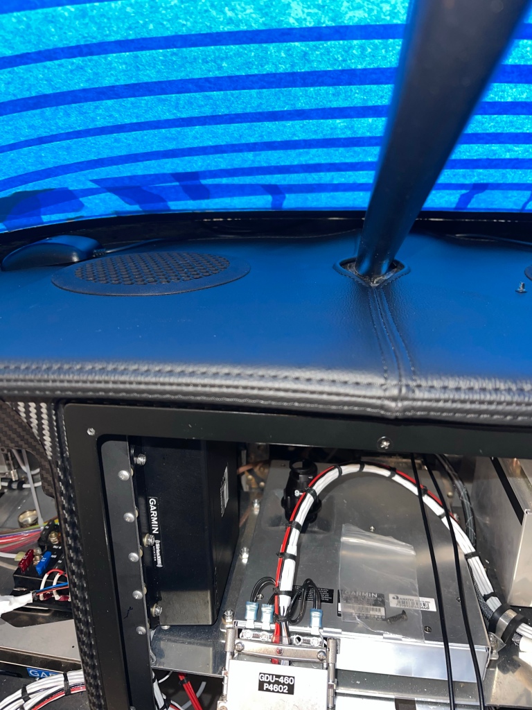
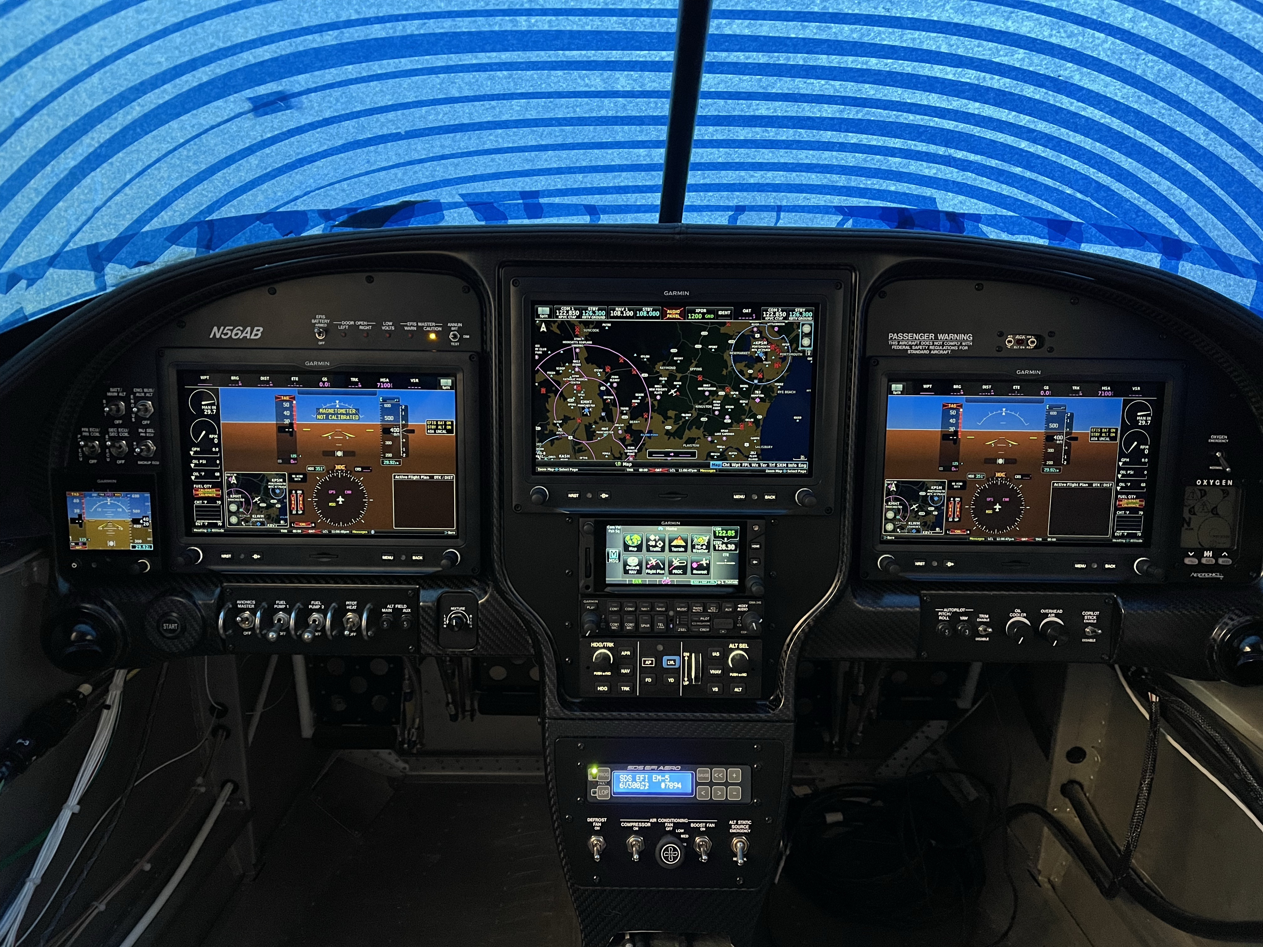
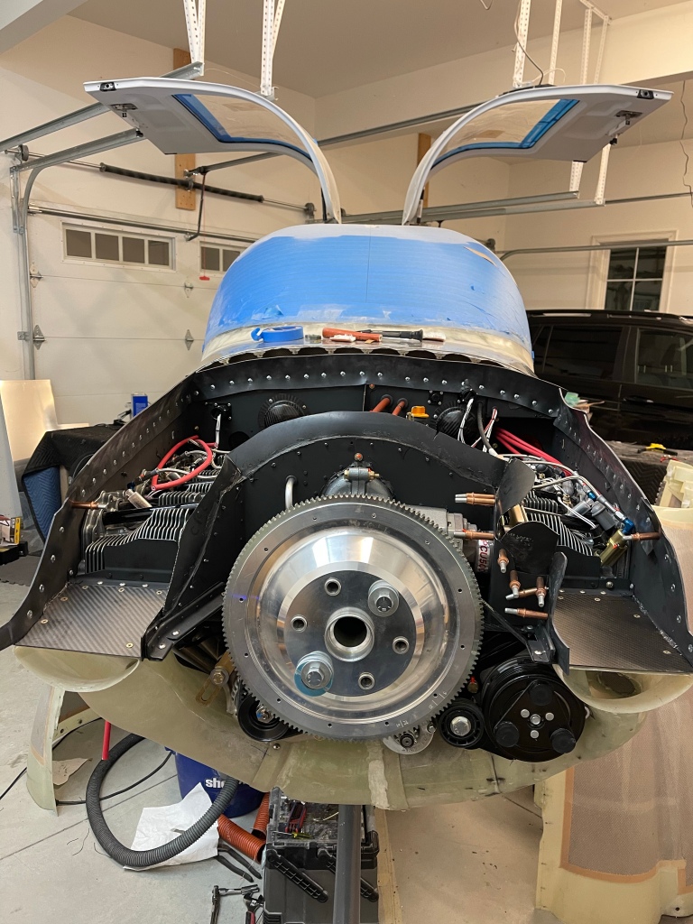
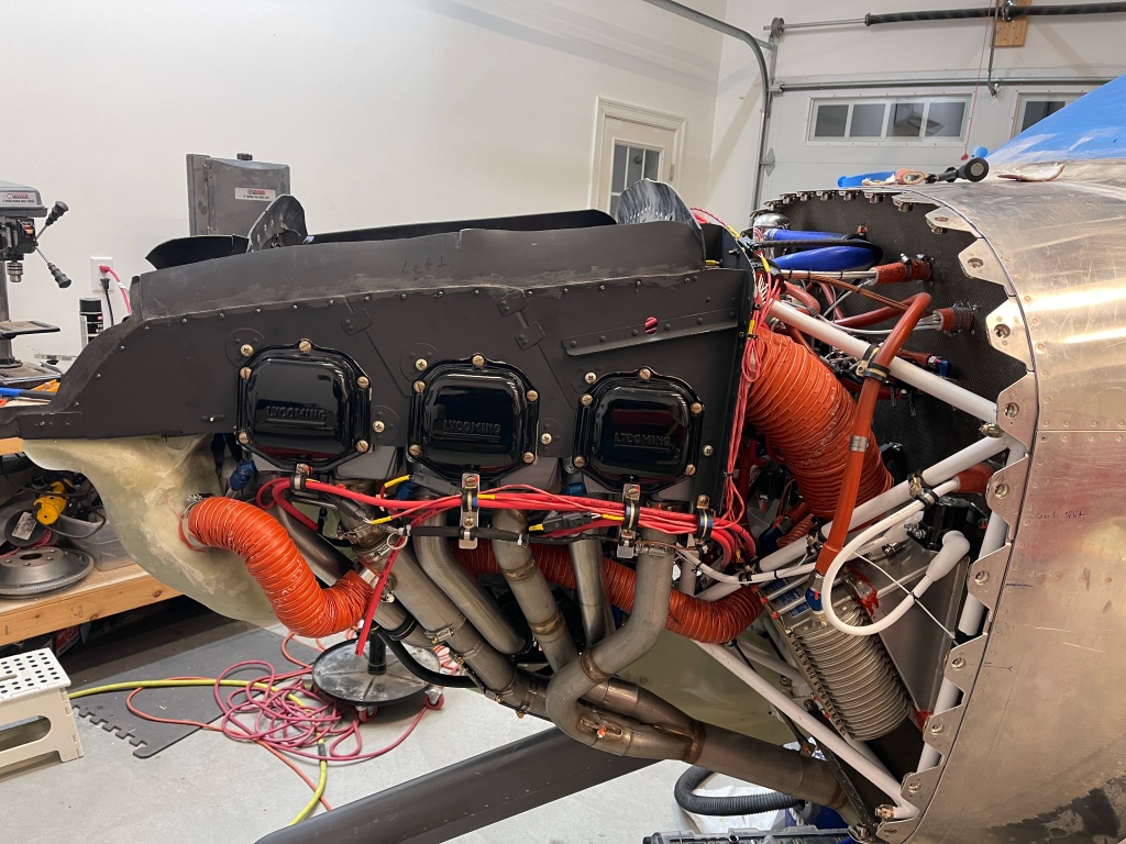
After spending some time double checking that the SDS system was seeing the flywheel magnets, programming all the gauges for green/yellow/red range markings, etc… I was confident that I was ready to try to start the engine for the first time. I used my truck to strap the plane to just in case something happened with the brakes. Fire extinguisher at the ready.. and I asked a fellow EAA member to come by to keep an eye on the engine while I ran it for about 3 minutes. I ran around 1000 RPM for a minute and a half or so, and then went to 1700 RPM and cycled the prop a couple of times successfully.

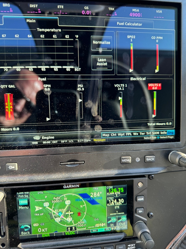
A quick snap of the engine gauges while it was running. Everything seems normal.

I let the engine cool down and then ran it one more time before putting it away for the day.

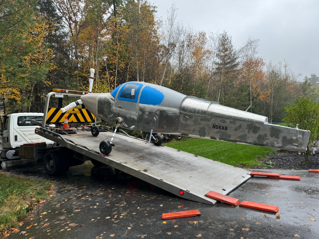
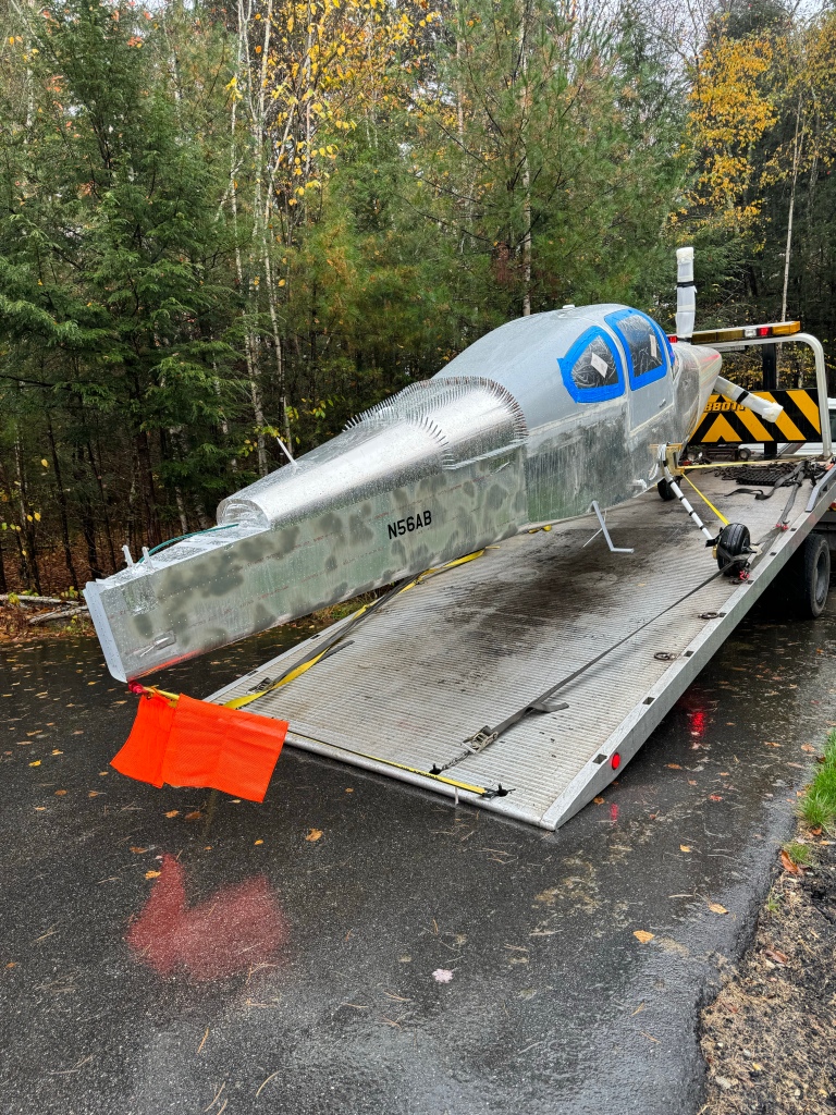
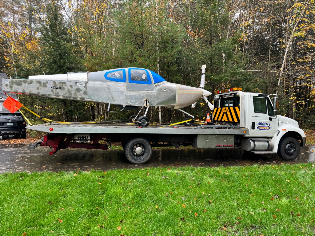
I’ve since been able to do some short taxi tests to set the brakes and also calibrate the magnetometer. Now it’s time to do W&B and get ready for the inspection.

Wings finished up

I test fit the fuel supply and return lines in the wing roots. Everything looked good once I clocked the sidewall bulkhead fitting downward a bit. I plan to put some tubing on the fuel line to avoid abrading the spar and side skins.

Left side before return line clocking.
Looking at the supply shutoff/filter setup.
Looking up on the whole supply line/filter
Right side after clocking

I then went down the road of finalizing my rigging. Everything went well except for my elevator rigging, which was somewhat expected. I was fighting a couple of different things. The first was that my stick hits the switches on the Aerosport panel, like so many before me. Some end up bending their stick to get more clearance. I decided to solve it by adjusting the forward and aft stops as well as changing the aft rod end of the forward (F-1089) pushrod from a MD3614M to a MD3616M to get more thread length to allow me to unscrew it more, resulting in the stick not going as far forward, while still having enough thread engaged in the pushrod.

Additionally, I was very close to needing to do the elevator stop service bulletin. So I took the opportunity to do that as well. To do these changes, I needed to take the rudder and Vertical Stab off to get better access.

Unbolting and unriveting the original aft elevator stop.
Stop completely off
Showing the elevator horn angle and how close it is to being able to jam on the stop.
New aft elevator stop installed to address service bulletin and adjust travel as needed.

I also installed a forward stop as well to help further limit the down stick travel by limiting elevator down travel to the min of 20 degrees.

Horn sitting against new forward stop installed

I then battled another issue with the control stick travel and a bolt head hitting the control column mount. This seems to be due to the angle of the stick weldment not being 70 degrees. It is causing the travel in the space cutout for the aileron pushrod to be biased forward as shown below.

Stick aft rod is completely forward
Stick forward only 3/4 travel in slot

Van’s tells me that this is usually due to the pushrod lengths being off. So I spent a ton of time removing all 3 of my pushrods and re-checking their lengths. They were really close as they were. Then working on setting things up properly from aft to front. At the end of the day, even with the stock measurements of the pushrods, I still have the same issue, so that is not the root cause.

Below I show the interference with the bolt and the mount.

You can see where the bolt was hitting.

So I decided to carve out a half moon as shown above in the mount to create clearance for the bolt. At least one other builder has told me they have seen this a bunch of times and done the same thing.

One other problem that resulted from this forward bias, is that the aileron pushrod that connects the 2 sticks through the tunnel was rubbing on my fuel lines as shown in the video below.

There was no possible way to move the lines forward anymore due to me having a brake line in the way.

In talking with Tom, I asked him to make 2 new lines for me that were 1/2″ longer to solve this issue.

New lines in place and rubbing problem solved.

With that saga behind me, I then bolted the wings on permanently. There are 8 bolts holding each wing on.

I also finished wiring the wings. Below is the air temp sensor under the 2nd access panel on the right wing.

Wingtips were also installed and tested out.

Now there are a couple of things left to finish up and then it’s time to get ready for my inspection. Calibrating gauges, fuel tanks, doing fuel flow tests, etc…

Tail and Wings

Lots of progress since moving to the hangar. It started by getting the tail pieces back on.

I then worked to get the emp fairing cover trimmed and in place and matched drilled to the holes in the metal using a strap duplicator. Then added nutplates so it can be held down with screws.

I needed to double check the nose wheel nut break out force and get a cotter pin installed. I really should drill a hole in the floor to thread a ring into for the strap, but I was able to use some blocks I had lying around and my creeper to pull the tail down, lifting the nose wheel off the ground.

I also spent an inordinate amount of time trying to bleed my brakes. In the end, I had to use a garden sprayer type setup to be able to build up enough pressure to push the hydraulic fluid from the brake caliper all the way up to the cylinder on the firewall. All other methods I tried (oil can, and also a vacuum bleeder from the top) failed to be able do the job.

I knew when I got my hangar that the single halogen light was not going to be enough. Still, in order to make progress, I made due with the use of some portable lights in the area(s) I was working. One day the bulb burnt out and rather than replace it, I took it as a sign that I needed to stop and just upgrade the lighting in the hangar. Below is the result of adding some new LED lights.

Once my ZipTips were done at home and before the first snow, I was able to get some help to transport the wings to the airport and subsequently get them onto the airplane!!!

Since getting the wings on, I’ve been able to get the flaps and ailerons on and rigged.

I’m now working on finishing up section 44 which is mostly about wing root fairings, fuel tank vent lines, and connecting the fuel lines between the tanks and the fuselage.

Flap connected
Aileron push bar connected.

In testament to the user friendliness of avionics these days, Declan seemed to pick up on how to use the EFIS right away. 🙂

I used some of the soft aluminum tubing to make the vent lines for the tanks as shown below.

So what remains is to finish the wing root fairings and get my fuel lines connected. Then I will need to take the wings off one last time to debur some things and finish some nut plates on the tank. Then I can bolt the wings permanently and finish up the electrical wiring.

After that it is mostly getting ready for first engine start and preparing for inspection.

Houston, The Eagle has landed!

Some additional tasks to finish up in prep to move to the airport.. Below you can see the small wrench I had to grind down in order to fit into the very tight spot and tighten the top arm of the main alternator. This had to be done after the prop was installed.

I had another tech councilor visit and he reviewed my FWF wiring/plumbing. A couple of minor suggestions for changes were made. One thing we discussed is getting the prop governor cable able to hit the stops on the governor itself before the lever in the throttle quadrant hits. I was having a hard time with this specifically. No matter what I did I could adjust one way and hit that stop, but not the other and vice versa. In the end I was able to rotate the face of the governor after removing the safety wire and loosening the face plate screws to fix the cable geometry issue. It just couldn’t pull aft and downward.

Working on getting the throttle and prop cables to hit the stops fore and aft while also having a little extra between the control lever and the end of the slot it travels in.

I also needed to get the AC hoses hooked up to the compressor and the dryer. In order to do this and charge later, I wanted to make sure that a vacuum could be held and that there were no leaks. I followed the procedure in the Airflow systems manual for evacuating the system. I hooked my gauges into the high and low side hose ports and pulled a vacuum on the system. I let that run for 10-15 minutes and then shut the vacuum pump off and let things sit for 30 minutes.

Gagues showing a vacuum.
High side hooked up to the port.
After 30 minutes still a -1 bar vacuum being held. Success!!

I also built and installed my light control circuit that turns the lights on when the doors open. Quick couple pictures with the main flood light and baggage area flood lights turned on by that circuit.

I the completely buttoned up the airplane for transport, getting the aft skin in place, cowling on, and speed tape on major openings because rain was in the forecast.

RV-10 plate to cover the side cowl pin.
Ready to go!

Then the day came.. I got the plane moved around so I could get it out the middle door of the garage.

Not the best day.. A decent example of the rain before we started loading and the speed tape doing a decent job of keeping it out of the plane.

I helped the driver get the plane in position and also kept the nose wheel straight with the tow bar as we pull the plane up onto the ramp. With the castering nose wheel, this really needed to be done to keep the plane coming up the ramp straight.

Nosewheel on!
All the way on. Now to tie down.
Mostly secured.
Flagging the minor overhang.
Ready to go!
On the road.. nerve-racking ride behind my baby!
We’ve arrived safely!
Offloaded into the hangar!
Another angle.

Now work has started on getting the tail pieces on. I’m still finishing up the wings bottom skins and ZipTips at home. It’ll be good to be able to work some at the hangar on the emp, while I still make some progress at night from home for the next few weeks.

Horizontal stab is on and elevator trim cables fished through.

Working the punch list

I’ve gotten down to a short enough list of things to do, it was time to write them all down and formulate an approx. schedule to move to the airport. A Punch list of sorts. That approximation had me moving on Oct. 1st. I’m still within about a week of keeping to that schedule. Below are lots of the items that I’ve checked off that list.

  1. Ask Van’s for a bill of sale, fill out registration paperwork, and apply. Done!

I do have to say, the FAA was rather quick. I know that they expedite new registrations, but still they were quick. The tracking said they received my paperwork on a Sat. So figured no sooner than Monday would they look at it at the earliest. My mid week I noticed they cashed my check. By the end of that week, my info was live with an online lookup, and by the end of the following week, I had the paper cert mailed and in hand.

I needed to still drill holes in the cabin top and countersink for screws for the front seatbelt attachment. I wanted to do this before getting the interior done going as well as needing to locate this hole through the headliner material used on the rear ceiling. You drill a 5/16″ hole in the center of the reinforced section of the cabin top. Then countersink it. I bought a countersink bit just because this hole is so large and I didn’t have a bit that would properly do it.

Left hole drilled and countersunk
Screw fits flush
The Countersink bit I bought for these 2 holes.

I then started working on interior items. I got the new McMaster door seal in place and installed the door handle plastic.

I then needed to install the seats, but first up were the seat rails. These are pretty straight forward, however, I did do one useful mod to easily remove the seats. I took the seat stop bolts out, placed the out-most rail in place and drilled 1/4″ holes into the seat pan below. I then installed nutplates. This allows you to simply install the aft seat stop with AN-4 bolts (slightly longer bolts are needed) from the gap between the door and the seat with a socket. The seat then glides backwards off the tracks and can easily be taken out. I also took out the plastic slides in the rails themselves and cut the first 1/2″ off to help get the seat tilted down a bit earlier to clear the flap tube cover.

Below is a picture of the seat rail sitting next to where it goes and the 2 new holes with nutplates drilled.

Nutplate mod on seat pan
Seat rail stop installed and is easily removable to slide the seat out.

I also installed the Aerosport Products seat levers to have the seat adjustment knob just under the front of the seats to more easily get to. I didn’t seem to take pictures of that install.

Then I installed the front seats.

Sticks and stick boots were also test fit.

I will say I’m up much higher than I’m used to. I’ve gotten so used to just sitting on the seat pans themselves.

Testing out the seats
Front seats in and avionics on.
Rear seats are now installed.

I then got the seat belts installed and the center console loosely in place.

Before I could get the front seat belts anchored to the cabin top, I had to install the Aerosport Products headliner onto the previously trimmed fiberglass substrate. Headliner adhesive from the autoparts store was used to adhere the fabric. I followed the videos on how to make cuts and wrap the material around the backside of the substrate dealing with the inside and outside corners.

Material on substrate
All finished up with the window gasket installed.

I then used some various widths of velcro to install this into the rear portion of the cabin top as shown below.

Headliner material installed.
Just had to take a fuller pic of the panel while I was sitting in the rear seats

Then some things to finish up in the wings prior to riveting on the bottom skins. I installed the aileron trim motor and springs along with the roll servo.

Roll Servo
Spring of the aileron trim.

Then I mounted the prop once again and got it safety wired and the spinner installed.

Panel is Powered!!!!

Continuing from where I left off. Wiring continued… Pulling wires to where they need to go. Cutting to length, stripping, crimping a pin on, and inserting into the connector.. Rinse.. Repeat! It’s always a fun time contorting myself </end sarcasm/> on the front seat area to get underneath the panel..

Working on some wiring behind/under the panel

I got the remaining GPS antennas installed.

GA35 between the doors.

I also got the switchpod finished up and wired down the A-pillar conduit.

Closeup of switchpod

I installed the GA-57X on the aft metal portion of the airframe. Just behind the AC evaporator to avoid interference.

Inside view of XM/GPS antenna
Outside view of the GPS antenna

One other thing I wanted to do before closing up the panel was to put the leather glareshield material in place with the two GPS pucks mounted on top of it. Below you can see me getting it lined up properly and the final product.

Getting the material aligned
Wider view of it all done and tucked under/between the glareshield overhang and the carbon panel.
Closeup to see the detailed stitching. Also a defrost fan grate in place.

I then installed the Pitot static and AOA tubing, distributor blocks, and connected them up to the G5, GSU25’s and the alt static switch. I then mounted all the avionics back into place in the panel.

I also decided to pin out the harness that will go out in the right wing. It houses the roll servo and magnetometer. Without it the CAN bus wouldn’t have been terminated properly and communication errors would have happened. I have those things laying in the footwell for now. I’ll have to depin from the CPC connectors later to route the harness through the wings, but that’s easy enough.

A number of triple checks to make sure I didn’t see any shorts between power and ground and making sure +12V was connected to the + side of the battery and negative to negative.. The moment of truth came…..

The panel powered up and everything seems to be working!!! A bunch of wiring work to get to this point, and it represents another major milestone in my build.

I really can’t say enough about the work that Aerotronics did to build this panel. They make it really easy to put it all together.

Now on to pushing forward and getting the remaining pieces finished up so I can get this bird to the airport and signed off to fly!

Wiring

Not too many updates recently. I’m at a point where it gets harder to take meaningful pictures. So here’s a photo dump of some of the more significant updates over the last couple months

I worked on finishing up the forward tunnel by wiring the fuel pumps and getting the transponder antenna doubler installed with the help of a fellow builder. I then got the cover on and secured the throttle and prop cables and some wire bundles for the headsets in the center console.

I cut out the rear portion of the arm rest where the jacks for the rear passengers and a USB charging port.

The metal plate to cover up the hole I cut and house the jacks.

I also cut holes out in the plastic insert in the arm rest for headset jacks for front passengers.

Jacks installed.

I also installed the 2 GPS pucks on the glare shield in front of the defrost fans.

Left side of the panel area.

Lots of the panel is connected to the rest of the airplane with CPC connectors. Here, I am wiring the P1 connector which houses things like the master contactor switch, starter relay, alternator regulator connections, flap motor connections, fuel senders, door sensors, pitot heat, and boost fan for the AC.

P1 wiring complete.

Secured into place with a clamp.

Wiring like the P1 wiring will continue.. Next post will likely be when I get to the point of powering up the panel for the first time.

FWF Done!

Wow.. What a ton of work! I’ve now completed all the Firewall Forward plumbing and wiring. The only thing left to do is to put spark plug ends on the wires and maybe tidy up a couple of wires, but outside of that.. I’m done. I also took a little extra time to revisit my baffle material seeing I wasn’t completely happy with it the first time. I changed the left, right, and aft material so each was one contiguous piece of material. Previously they were broken into 3 pieces. The aft part had some puckering that I didn’t like as well, so was addressed with this update.

The next couple of pics are from the front.

The right side of the engine.

Boy does it really get busy in the space between the firewall and the engine. Especially when you have 2 coil packs for the spark plugs.

The left side of the engine.

Again busy busy.. It really took so much time not only to wire things, but to come up with reasonable routes and securing things.

Now its back to finishing the inside wiring and getting my panel powered up!

FWF wiring never ends

Mostly been focused on FWF wiring. There are lots of connections to be made and properly securing the wires seems to take considerable time. Fabricating brackets.. etc..

Below you can see the metal L brackets I made along with a short straight metal piece to secure the #2 starter cable to the oil sump. The straight metal piece allowed me to mount the adel clamp for the #2 wire inwards, sort of on top of the sump. The adel clamps down lower allow for the lower voltage signal wires, mainly CHT and EGT, but also throttle position sensor wires to be secured.

Left side brackets

I also secured the AC hoses FWF along with putting the ends on the compressor side of the hoses. I secured the hoses to the forward-most intake tube, a plate secured to the left side of the cold air sump.

Left side AC hoses

The hoses connected to the FW and secured (although not in sight) to another metal bracket attached to the bottom of the cold air sump. I may also secure them to the engine mount in the middle of the run shown below.

Right side AC hoses
AC hoses ready to be connected to the compressor

CHT probes were screwed into their locations in each cylinder. I then got to locating the EGT probes making sure they have clearance seeing they stick straight out of the exhaust pipe. I targeted 2 1/4″ down from the flange. I was able to locate 2 of the 3 on the inside of the pipes and #2 needed to be pointed outside due to the angle of the pipe and the heat muff being on this pipe giving few other options.

Drilling a hole for the EGT probe
Probe secured in place
Left 3 pipes have EGT probes installed.
Left side coming along

I’ve run spark plug wires to their destinations. The left coil pack services the top set of plugs and the right coil pack services the bottom plugs on each cylinder.

Top Right spark plug wires routed.
Top Left Spark plug wires routed.

At this point the left side is just about complete. Still need to finish the spark plug wires and the Tanis wiring to each cylinder heat element. Time to work on the right side.

Left side nearing completion.

Below are some other pics of having a bung welded into the right side exhaust collector for the SDS O2 sensor installation spot. I had a local guy TIG weld this on for me.

O2 sensor bung.

I also split the forward tunnel cover into 2 pieces like most builders do with an Aerosport center armrest/console. I also mounted my bracket for the throttle and prop cables.

In unrelated news.. I received my Aveo Engineering Zip Tip wing tip light units. I ordered these at Oshkosh, so 6-8 weeks turned into 6 months wait time, but they are here and they look great!

Zip Tips!

Lower instrument console and armrest

Prior to starting to wire all the FWF stuff, I decided to get my lower console with its side panels and the center armrest with the fuel selector and throttle quadrant installed. The main reason for this, is I need to measure for my throttle and prop cable lengths and I can’t do that with out placing the quadrant.

I first mounted the lower instrument panel console and got it match drilled to the left side panel. The same was done to the right side panel. I used a strap duplicator to match drill holes into the side panels along the top of the tunnel so we can secure them to the existing hole/nutplate locations. Once that was done, I located the center armrest into position and matched drilled 6 holes (3 per side) also to the existing screw holes on the top of the tunnel.

I then cut out the armrest for the throttle quadrant based on the scribe lines. I placed the quadrant into rough position in the armrest while it was upside down and taped it down. I placed masking tape down on the tunnel cover approx. where the quadrant will sit. Then with the center armrest placed down and screwed to the tunnel cover, I marked the legs of the quadrant on the masking tape through the top opening of the armrest. I then removed everything and drilled holes and bolted the quadrant to the tunnel cover. The holes are slotted, so you have some fore/aft as well as up/down adjustment. Getting it pretty close was sufficient. The harder adjustment was the up/down as you don’t have access to the screws with the armrest in place.

Once that was done, I had previously placed the Andair selector valve more or less in the stock location. So I drilled the hole provided by Van’s up to 3/4″ round hole for the Andair extension arm to come up through the tunnel cover. The extension was pretty close to centered on that hole, so I left it as is.. I used that hole in the tunnel cover to locate and drill the hole in the carbon armrest for the selector.

Throttle quadrant and fuel selector valve hole cut

Then the extension arm was cut to the proper length following the Andair instructions and the bottom part of the selector was placed onto the arm and test fit to the hole in the armrest.

The faceplate was put into position and I used the 4 screw holes on it to drill holes into the armrest. I prefer the orientation to be as shown below. I feel like it’s a little more clear this way as the selector will be pointing left and right for selecting the respective tank. Mounting the faceplate so that the “Lift knob” is right reading, so to speak, would have left tank selection pointing really left and right tank selection still pointing left, just not as much.

In order to be able to potentially remove the center armrest without removing the lower console nor the fuel selector valve, I used nutplates on the piece that sits under the selector valve as shown below. A couple of the holes on the armrest has to be oblonged a little bit to make the screws meet the nutplates properly, but that isn’t a big deal as the faceplate covers that area.

Nutplates on face plate screwdown plate

With all that done, below are the end result at various angles.

I was then able to measure for my cable lengths. I used some vinyl tubing I had lying around to emulate the route for both the throttle and prop cables. I marked around the mid point of the threaded part of the bearing/tie rod terminals and made sure the controls were both full deflection in the same direction (fwd/fwd or aft/aft), I then pulled the tubing out and measured the marks. I did add a couple of inches for some slop or slight variations in the install path that I measured to.